Have you ever played the brutal drinking game called the Centurion? It goes like this - have one shot of beer every minute for 100 minutes. It may not sound like much, but if you think about it, a 30ml shot 100 times is 3 litres of beer in a little under two hours.
The whole deal is powered by a 12v SLA rechargeable battery which sits inside the case.
Misc photos of the whole process with bonus video at the end:


Anyway, I've played this a few times and the biggest problem is keeping track of time and who has drank what. Usually you need a timekeeper who isn't playing to ensure that all drinks are taken and that we drink at the appropriate time. Well, for an upcoming bucks weekend (mine), I decided to remedy this.
I build it into an old tool case I had lying around. There are 8 double seven segment displays to keep track of players scores, all driven by 595 chips attached to transistor arrays. I decided not to use a 7-seg driver chip because it would have been more of a pain to solder. The 595 and ULN2803 transistor array can pretty much be mounted side-by-side. Since I didn't etch my own board, this means less point-to-point soldering.
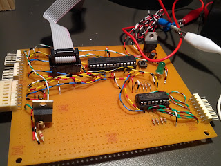
The whole project is driven by an Atmega8 chip and coded via my Linux server. The main board uses a 195 to read the state of all of the push buttons. I count overflow interrupts to know when 1 second is up, and have a pause button hidden under a missile switch - you wouldn't want to accidentally pause this game. I also built in a programmer pin-header to program the atmega chip in situ.
A large double 7segment display is used for the main timer - it actually required 7.something volts to run properly, so that was a pain. The original plan was to have another of these on the right to count drinks elapsed, but I ran out of time.
I picked up some automotive LED strips as well as a home alarm screamer to notify the players when it's time to drink. A potentiometer regulates the volume of the screamer, as well as some gaffer tape - it was particularly loud to begin with. Fun fact - screamers sound weird when you change the amount of current going into them.
The whole deal is powered by a 12v SLA rechargeable battery which sits inside the case.

The main-board

Back of the main-board

The timer display

Back of the timer display

One of the scoreboards under construction

One of the scoreboards under construction

Completed scoreboard

Back of a completed scoreboard

Components ready to be mounted

Underside of the base.

Inside of the case - almost complete!

I added some dry-erase stickers so we don't lose track of who is who.

Closed for travel.
Comments