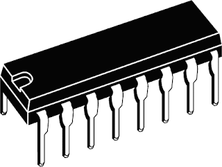
This is the part of the blog that gets a little programmer-ey - this post will outline how the 4094 chips work.
Firstly your basic stamp/parallel port/whatever that you are using to control the pinball machine only has a finite amount of outputs (probably 8 or 16 or something). The parallel port has 8 (more if you cheat a bit - or so im told) and my basic stamp has 16. Hobviously, this is well less than what im going to actually need if i want to control 40-odd lights and 20-odd switches. Standard pinball machines use a light/switch matrix, which from what i can guess, strobes each row of the matrix in order from top to bottom while turning on or off the required columns to light up the controlled playfield lights. I speculate that as this happens very fast and due to the fact that its using incandescent globes that take a while to turn off, it can give the illusion of always-on lighting. Anyway with the light matrix idea for up to 49 lights, i'd need a 7x7 matrix, which would still take up a good 14 pins. A good saving, but still too many.
Myself and some former workmates had once tried to make a pinmame hw board unsuccessfully, and had shelved the parts. I dutifully ninja'd these parts home and started trying to figure out how the 4094 chips worked (note that 595 chips will do pretty much the same thing, but i either couldnt find them or they were more expensive).
Off the top of my head the exact chips i had were: 74HCT4094. The other similar chip is the 74HC595 (more info and comparisons on the two from here: http://homepages.which.net/~paul.hills/Software/ShiftRegister/ShiftRegisterBody.html. Also note that i learned most of what im spewing out here from that website.
Basically what the chip does is take some input from 4 (thats right, 4!) pins serially, and set a bunch of outputs (LED's) states. For example if i have 8 led's and i want every second one on, i (and this is abstracted and pseudocoded) say: "OFF,ON,OFF,ON,OFF,ON,OFF,ON". The chips goes 'ok thats the pattern, ill just set my output pins to these states - no worries'. In real life (irl) this is slightly more complicated, but thats the basic gist of it.
Ok so there are 4 input pins that we care about ont he 4094. These are data, strobe, Output enable (OE) and clock. Additionally, im powering all this from +5v DC (this includes all the led's). The chip has 8 parallel outputs, AND is so cool that you can connect multiple 4094's to each other and get n (well some large number - but the bigger it is, the slower stuff will work) led's working all from the same 4 pins!. I have 6 all lined up and working in mine thus far.
Lunch time is over! Detailed info on how to use the chips coming up later!
Comments